Exist

Managing the Thirst for Power

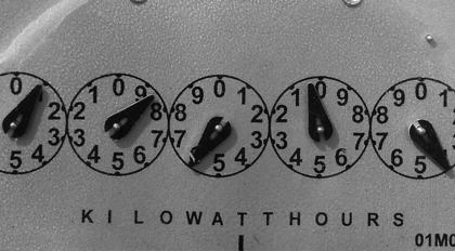
Data center power consumption is a critical issue faced by both small and large organizations. Underscored by estimates Lawrence Berkeley National Laboratory that data centers in the United States were to have consumed 70 billion kilo-watt hours (kWh), or about 1.8% of total U.S electricity consumption. The impact of growing power consumption has forced organizations to allocate valuable CAPEX in more efficient data center technologies.

Data center managers face the daily challenge of managing power consumption and its impact to OPEX and CAPEX. Global data centers measure their power capacity and consumption in megawatts, not watts. Thus incremental, “one-watt-at a-time” strategies may seem like a small drop in the bucket, but given time and scale, they can reduce power consumption.

Critical load generated by IT equipment, such as servers, routers and switches are only part of the power equation. Ancillary power for cooling, lighting, and other equipment must also be included in the data center power consumption equation. Not all that long ago, data centers planned on a 1-to-1 ratio between IT critical load and support power. Meaning that for every dollar spent on critical load, one dollar was required for support power. This model did not scale well to the era of massive cloud data centers.

Overall, today’s data centers tend to operate with efficiency metrics between 40% and 70% of the critical load. Meaning that for every 1 watt of IT critical load used, an additional 0.4W to 0.7W of support load is used to cool and maintain the data center. Given these data center economics, reducing the IT load by 1 watt can really mean reducing to total power load by 1.4 to 1.7 watts.

Max Power Consumption

SFP+ 10G

QSFP+ 40G

QSFP28 100G

DAC (one end)

0.1W

< 0.5W

< 1W

Short Reach Transceiver (each)

0.9W

1.5W

3.0W

That is where looking at network cabling power offers opportunities for incremental efficiencies. Current data center trends toward top-of-rack switching are driving efficiencies one watt at a time. Conventional top-of-rack architectures use direct attached cables, or DACs, to connect servers in a rack to a switch in each rack. DACs are pre-terminated copper cable assemblies with a transceiver pre-terminated on each end and installed into the SFP+ or QSFP ports in a switch or server. In addition to being lower cost than a transceiver and structured cabling solution, DACs offer efficiencies by not performing optical to electrical conversion inside the module. The cost savings from not operating a laser offers, at bare minimum, 70% power savings over a short reach transceiver. Case in point of a 10G SFP+ DAC cable. The combination of both ends requires 1.5W less power than two 10G SFP+ SR transceivers. 40G and 100G connections see even larger power consumption advantages with DAC cables.

Applying these numbers to the real world, we need to answer the question, “In a world with 10-megawatt data centers why should data center managers care about 1.5 watts?”

Like compounded interest on money, power savings in the data center also compounds. As we include the power efficiency metric of the data center, we also save on support power in the data center. In this example, for each 1.5W of IT power savings, another 0.6 to 1.05 watts of support power is saved. Offering a net savings of 2.1W to 2.55 watts saved per connection. A data center with a top-of-rack architecture and 1000 cabinets could realize up to 21kW power savings using DAC cables.

The net effect on operating expenses comes in calculating the kilowatt hour savings multiplied by the cost per kilowatt hour.

The cost of electricity may vary by up to 200% depending upon country and season. The June 2018 U.S, Energy Information Administration proves out this assumption, data centers with higher power costs stand to gain the most from top-of-rack DAC connections.

Region

Average Industrial Utility Rate per kWh June 2018

Savings ($)

New England

$ 0.12

$ 23,631.02

Mid Atlantic

$ 0.07

$ 13,050.25

West North Central

$ 0.08

$ 15,253.79

Mountain

$ 0.07

$ 13,031.26

Pacific Contiguous

$ 0.11

$ 20,344.72

South Atlantic

$ 0.07

$ 12,613.34

East South Central

$ 0.06

$ 11,625.55

East North Central

$ 0.07

$ 13,240.21

West South Central

$ 0.06

$ 10,675.75

Pacific Non-Contiguous

$ 0.24

$ 45,267.47

Very few of today’s massive data centers are deploying 40G and 100G for top-of-rack connections. However, those that do or may plan to stand to realize even greater savings!

40G QSFP+

100G QSFP28

DAC Savings/ connection

2

4

W

Power Efficiency

0.4

0.4

Savings per connection

2.8

5.6

10 connections/rack

28

56

W

1000 cabinets

28

56

kW

kWh/year

175200

490560

kWh

Savings by Region

New England

21,794.88

61,025.66

$

Mid Atlantic

12,036.24

33,701.47

$

West North Central

14,068.56

39,391.97

$

Mountain

12,018.72

33,652.42

$

Pacific Contiguous

18,763.92

52,538.98

$

South Atlantic

11,633.28

32,573.18

$

East South Central

10,722.24

30,022.27

$

East North Central

12,211.44

34,192.03

$

West South Central

9,846.24

27,569.47

$

Pacific Non-Contiguous

41,750.16

116,900.45

$

Reducing data center power consumption one watt at a time with direct-attached cables is not a futile approach in the race against rising power consumption. The cost models show real-world OPEX savings over transceiver and structured cabling alternatives.

Our solution experts can help you no matter the project complexity. Request a quote or contact us to learn more today.

400G - Which form factor? (QSFP-DD, OSFP, CFP8)

Trends in 400G Transceiver Form Factors

The adoption of new form-factors and features is nothing new with the dawn of new technologies. The 400G era is upon us and like previous technology cycles, the 400G market will feature different transceiver form factors targeting specific network applications.

Next-generation transceiver form factors share three attributes: small in form-factor, low power consumption, and interoperability between all system vendors. Understanding how the 100G transceiver market developed will help us understand the introduction of 400G technology.

Service providers required a pluggable transceiver for long reach and dedicated technologies, such as coherent detection. The data center team required a solution for a short reach (up to 2KM) application with both low power consumption and low cost.

The CFP form factor was the first 100G pluggable transceiver, providing support for both short and long reach applications, but was very large and consumed a high amount of power (12W). As technology and components improved in size and power consumption, the smaller CFP2 and CFP4 were introduced to the market. Despite technology improvements, embedded coherent technology for 100G and 200G are still only available today on CFP and CFP2 form factors.

In parallel, hyper-scale data centers with their phenomenal need for additional bandwidth capacity, have pushed the QSFP28 form factor (See our post, “A Missing Link,” for more) for various short reach applications (DAC, PSM4, CWDM4, and SR4). The QSFP28 has seen wide adaption and offers a much smaller form factor with lower power consumption than the CFP form factors.

Understanding the questions behind 100G applications is important in anticipating how 400G will be adopted.

  • Who needs the 400G pluggable transceivers?
  • For which application?
  • What about technology maturity?
  • Is there any interoperability with former form factors?

Following the same logic as 100G, the 400G is a priority for the large data centers and, at a lower scale, for service providers.

400G requires PAM4 modulation for transmission, making the reach more challenging. The initial 400G transceiver reach will be limited to only a few kilometers. Longer reach will require coherent detection and its support technologies, including amplification, and dispersion compensation.

Like 100G, 400G will see similar adoption based upon the intended applications. Most likely a dedicated form factor for the data center and another for longer reach applications. The early 400G technology development is avoiding the "intermediate" form factors (i.e. CFP2, CFP4) that 100G adoption followed.

400G will be introduced with two form factors for the access networks and data center.

  • QSFP56-DD (also called QSFP-DD for QSFP Double Density)
  • OSFP (for Octal SFP)

Both form factors are running 8x lanes of 50G PAM4 on the electrical side while the optical side can be either eight lasers of 50G PAM4 or four lasers of 100G PAM4. In the four-laser design, we add a "gearbox" converting 8x 50G PAM4 electrical to 4x 100G PAM4. (Also see our dedicated blog article: "From 50Gbps PAM4 to 100Gbps PAM4")

  • The QSFP56-DD is defined by the QSFP-DD MSA alliance (www.qsfp-dd.com) while the OSFP is defined by the OSFP MSA group (www.osfpmsa.org). The two form factors are similar but have three key differences:
  • OSFP allows more power (< 15W*) than the QSFP-DD (<12W*). The OSFP allows an early adoption because it's easier to release a technology designed for 15W than 12W.
  • The QSFP-DD port is backward compatible with QSFP+ (40G), QSFP28 (100G) and QSFP56 (200G). The OSFP port requires a QSFP to OSFP converter module.

The OSFP integrates thermal management directly into the form factor, the QSFP-DD does not.

*For more information in the our blog article "QSFP-DD vs OSFP, the match!"

Both QSFP-DD and OSFP are designed for intra-DC applications including DAC, AOC and optical connection up to 2km. Additional variants are in development to support data center interconnect (DCI) with longer reach and other technologies like DWDM super channel.

The CFP8 form factor, defined by the CFP MSA (www.cfp-msa.org), is radically different than QSFP-DD and OSFP:

  • Allowing up to 24W power consumption
  • It has 16x channels 25G NRZ on the electrical side (instead of 8x 50G PAM4 for QSFP-DD and OSFP)
  • Providing for an MDIO management interface (instead of I2C for QSFP-DD and OSFP)

With its large footprint and high-power consumption (up to 24W), the CFP8 is intended for transmission application. The initial version (CFP8 400GBASE-LR8) will support up to 10km, using 16x electrical lanes of 25G NRZ which are converted to 8x lanes of 50G PAM4.

Additional variants using coherent detection technology that will support up to 80KM are down the road. In addition to driving longer distances, the CFP8 opens the door to 800G. 800G is possible by a combination of 50Gbps PAM4 modulation DSP, coherent detection and multiplexing of lasers to the CFP8's 16x electrical lanes. Clearly, this technology is far off on the horizon.

The 400G era is upon us. Understanding technology applications will help us better understand the transceiver technology adoption.

Ambroise Thirion

Product Solutions Specialist

ProLabs to launch its innovative solutions to maximise network infrastructure and help operators to be 5G ready at NGON Europe 2019

Cirencester, UK, May 2019 – ProLabs, a global leader in optical connectivity, will unveil its pioneering solutions for next generation Data Centres and 5G networks at NGON Europe in Nice, 21-23 May 2019. The company will highlight the changes necessary for operators to prepare for the continuously growing capacity requirements and complexity of the future 5G network.

Debuting its new Optical Channel Monitor to the European market, ProLabs will showcase the EON-OMP-2, which allows for the remote monitoring of WDM wavelengths on optical fibres. The EON-OMP-2 will enable network issues to be identified quickly and without causing major infrastructure disruption whilst saving time. For fibre laid in locations such as rural communities or remote unmanaged locations, this has previously been a major issue.

“The launch of our new Optical Channel Monitor signifies ProLabs transition into complete solutions enabling our customers to manage their fibre and monitor capabilities laying the foundations for 5G evolution,” said Anthony Clarkson, Technical Director at ProLabs. “The EON-OMP-2 is the first product in the launch of our Active Solutions portfolio. When combined with our full range of compatible products, it gives utmost control over maximising infrastructure development to our customers at an affordable price with no compromise to the quality of data transmission that they demand.”

The EON-OMP-2 enables network operators to have a greater visibility into their network which can assist their operators, provisioning and monitoring teams. This innovative new product drastically reduces the time taken to troubleshoot network issues and can prevent engineers needing to travel to remote sites for troubleshooting purposes. The product can also be used in older legacy networks, where up-to-date record keeping of in-use wavelengths might be lacking.

Alongside the launch of its Optical Channel Monitor, ProLabs will be showcasing its solutions for 5G and Data Centre Interconnect including its range of SFP28 25G products, e-band WDM and transponder solutions.

Anthony adds: “NGON is the perfect place to introduce our new Optical Channel Monitor for the first time. Each year we have attended NGON, we have seen the industry welcome new innovative technology. The introduction of our latest product, the EON-OMP-2, combined with our 5G and Data Centre Interconnect solutions will present an exciting opportunity for operators to achieve greater network visibility and enhance their optical networks ready for 5G.”

NGON Europe 2019 visitors can learn more about ProLabs solutions for 5G and Data Centre Interconnect at Stand 24.

Press Release - ProLabs to unveil new testing solution to detect, locate and report fibre faults at Broadband World Forum 2018

South Cerney, UK. 16 October 2018: Leading optical transceiver specialist ProLabs will showcase its latest testing solution, which detects and locates breaks or faults in optical fibre cables, ultimately saving time and money for service providers at Broadband World Forum 2018, taking place October 23-25.

The latest addition to the ever-growing portfolio of ProLabs solutions, the EON-NSV-OTDR stands out from similar offerings as it quickly locates and reports any faults or issues within optical fibre networks which means the right team can be dispatched for the related problem quicker than previously before.

The solution works by transmitting a series of optical pulses into the fibre under test and extracts. From the same end of the fibre, light is scattered or reflected back from points along the fibre. The scattered or reflected light is measured and then analysed to locate the end of the fibre, the location and overall loss. This process allows engineers to detect if fibres are intact and to then deploy teams to fix the issues as and when they are found.

“Detecting problems within optical fibres is vital if a reliable network is to be maintained,” said Ray Hagen, Americas Product Manager at ProLabs. “The information that the OTDR solution provides can report on the specific problem that has occurred and highlighting the approximate location, saving time and disruption to often critical & vital services. This solution is addressing the ever-increasing demand for reliable network requirements, and ProLabs is proud to offer such a product at a cost-effective price point.”

The EON-NSV-OTDR solution is specifically designed to allow for not just OTDR testing of the underlying optical circuit but also the layer-2 and layer-3 services that may be running over it. Also, the solution contains custom hardware for the generation of test traffic, loop-back and analysis and can be configured to provide real-time monitoring of jitter and latency between the desired end-points in the network.

The benefits of utilising this device are necessary if operators are to ensure time wasted and costs are kept at a low level. The solution locates, stores and reports the number of faults and reflections detected, calculates distances to the faults, and reports the distance to the farthest fault. These features mean the Communicating Sequential Processes (CSP) can dispatch the right team for the right problem quickly and efficiently. Also, by minimising the detection time, the service provider can reduce operational costs not only by avoiding the dispatch of the wrong maintenance team but also by reducing the time to restore the affected services.

“Broadband World Forum is the best event in the world to highlight innovations in network infrastructure, and we are delighted to be back again this year launching another solution which can help improve already existing infrastructure,” added Hagen.

Broadband World Forum 2018 visitors can learn more about ProLabs technology at Booth A121.

From the mag: ProLabs' Zoë Binder on baking an innovative tech career

Zoë Binder, coding manager at ProLabs, chats to CommsMEA about women in telecoms, her job, background as a baker, innovation, and more

“Network infrastructure needs revolutionising to guarantee a successful 5G connection,” warns ProLabs at ECOC 2018

ProLabs attends ECOC 2018 in Rome to discuss the need for network infrastructure development and maximisation to support 5G deployments

ProLabs to unveil new testing solution to detect, locate and report fibre faults at Broadband World Forum 2018

ProLabs launch their new innovative product- OTDR. A cost effective solutions to support fibre infrastructure and Service Providers

ProLabs at Fierce Wireless NextGen Summit: “Utilise WDM in the quest to invest for 5G success”

Anthony Clarkson talks to the media at Fierce Wireless NextGen Summit about WDM for 5G success!

25G is the new 40G

25G networking has quietly become the building block of enterprise and data center network upgrades. The current wave of 100G upgrades are built on 25G lanes delivering cost-effective 100G networks. 40G networks will remain a staple in the enterprise and the data center for the short term, but 25Gs role in building future networks is bright.

25G upgrades in the enterprise and data center offer advantages over 40G. 25G, SFP28 transceivers offer the benefits of the SFP and SFP+ form factors (low power consumption, common footprint, and density) and use existing 10G cabling. Sporting a single 25G lane, the SFP28 also rolls nicely into future network upgrade standards. 100G QSFP28 and 200G QSFP28-DD each use multiple 25G lanes in their architecture.

In contrast to 40G, 25G is being introduced directly to the edge NICs and switches, rather than a line side upgrade. Unfortunately, simply installing an SFP28 transceiver into an SFP switch port does not simply upgrade a port to 25G. Edge devices must be upgraded to support 25G. Upgrading the sheer volume of edge devices in a network will require both budget and time. Advances in transceiver technologies are now available to allow enterprises and data centers to upgrade only portions of their network to 25G while deferring upgrades on other portions into the future.

Distribution Switch with SFP28 10G/25G Transceivers
Leading to 4 Edge Switches; 3 10G SFP+ and 1 25G SFP28

The new SFP28 10G/25G transceiver is dual rate, capable of connecting at 25G or 10G. When installed in a distribution or aggregation switch, the SFP28 10G/25G transceiver can connect over existing network cabling with either a 10G SFP+ or 25G SFP28 transceiver installed in edge devices.

This approach allows data centers and enterprises to align 25G upgrades of edge devices and NICs with time and budget constraints. SFP28 10G/25G transceivers are available in SR (OM3/OM4 multi-mode fiber) and LR (single-mode) variants.

Demonstrating the versatility of 25G, breakout applications separate the transmit and receive pairs from a QSFP transceiver to four SFP-type transceivers. QSFP breakout applications are prevalent in top-of-rack, end-of-row and spine/leaf environments. In 100G networks, aggregating four 25G network devices into one QSFP28 port offers power, port and reduced latency advantages over one-to-one port approaches. 100G to 25G breakout applications are supported by multiple solutions.

Leaf & Spine Architecture
Spine Switch with 100G SFP28 port to Leaf Switches with 25G port

Transceiver based solutions utilize existing fiber cabling to avoid costly plant upgrades. The QSFP28 SR4 transceiver accepts an OM3 or OM4 MPO-type connector with various breakout cables or cassettes that separate the physical lanes into four transmit and receive pairs to interface with SFP28 SR transceivers. The QSFP28 PSM4 transceiver takes a similar breakout approach but requires an angle polished single-mode MPO-type connector cable to interface with SFP28 LR transceivers. Transceiver breakout solutions are typically deployed in end-of-row and spine/leaf applications, leveraging existing 10G fiber cable infrastructure.

Direct Attached Cables (DACs) and Active Optical Cables (AOCs) are ideal solutions for new top-of-rack and end-of-row QSFP port breakouts. DAC and AOC breakout cables have a pre-terminated QSFP-type transceiver on one end with four SFP-type transceivers on the other. 100G DAC breakout cables are widely deployed in top-of-rack applications, connecting a top-of-rack QSFP28 switch port to four SFP28 ports. 100G AOC breakout cables are more common in both end-of-row and spine/leaf applications to overcome distance limitations of copper direct attached cables.

25G solutions offer enterprises and data centers an upgrade path aligned with future network technology while reducing the cost of network cabling upgrades.

Content written by Americas Product Manager, Ray Hagen

ProLabs urges operators to look at the management of fibres in order to future-proof networks and be 5G ready

Cirencester, UK, 29 May – With ever-growing capacity requirements and the complexity of the future 5G network, it is important for operators to invest in the monitoring and management of networks, in order to maximise network infrastructures and be prepared for 5G.

As the demand for increasing bandwidth and higher data rates create increasingly complex networks, more variables are introduced that decrease the average time to failure and increase the average time to repair, if a failure occurs. This coupled with the fact that site visits are expensive, time consuming and can be labour intensive in terms of repairs, means that operators are constantly looking for ways to identify network issues quickly with minimal disruption.

Monitoring the optical layer of a network is critical, particularly for fibre laid in locations such as rural communities or remote unmanaged locations. For remote sites with no personal presence, if a resource fails an engineer would be dispatched to the site to inspect whether the issue is with the resource itself or the infrastructure, which can be quite costly and time consuming.

“As consumers continue to demand increasing bandwidth and higher data rates, operators will be looking to invest in their networks to keep up with those growing demands,” said Anthony Clarkson, Technical Director at ProLabs. “This creates progressively complex networks which require proactive monitoring in order to prevent fewer downtimes of smaller duration. In turn this improves uptime and MTTR statistics but can also save money operationally.”

With Optical Channel Monitoring (OCM) the network monitoring team can determine the issue within a couple of minutes, providing valuable optical data for networks which can then be passed onto operators and maintenance companies.

OCM can be used both for provisioning and troubleshooting purposes. Through using OCM, network operators can manage fibre and monitor capabilities, giving them greater visibility into their networks which can assist their operators, provisioning and monitoring teams.

“Network operators worldwide have already started to realise the potential that Optical Channel Monitoring can bring to their networks,” added Anthony. “OCM currently monitors the full Dense Wavelength Division Multiplexing (DWDM) channel range and with Coarse Wavelength Division Multiplexing (CWDM) monitoring scheduled for the first quarter of 2020, operators will continue to have greater network visibility and enhance their optical networks ready for 5G.”

Anthony Clarkson will be discussing the importance of monitoring the optical layer of your network in more detail at the LINX105 event on 30 May at 11.05am.