In data centers and networking environments, the presence of numerous cables often poses a challenge when it comes to identifying, tracing, and managing top-of-rack connections efficiently.
ProLabs' new blue and black color-coded pull tabs on QSFP28 100G Hybrid DACs provide a simple yet effective solution. Technicians can easily visually identify and organize cables based on their distinct colors, streamlining cable management processes. This not only reduces the risk of misconnections but also accelerates troubleshooting procedures.
Data center operators and network engineers often face frustrations by the limited supply of compatible OSFP solutions. Network elements supporting 400G are limited to a few key network equipment manufacturers, preventing widespread availability of innovative solutions.
ProLabs' OSFP 400G PLR4 transceiver not only addresses the supply gap but reshapes it entirely. Designed to seamlessly aggregate 100G LR1 to 400G ports and enhance network efficiency, our product serves as the vital link, closing compatibility gaps and guaranteeing seamless interoperability with Arista platforms.
Reducing deployment costs is critical for the success of fiber-to-the-home deployments. Fiber-to-the-home service providers must meet business requirements, aiming to increase customer density and serving area sizes, all while future-proofing their networks for next-generation services. Previous generations of PON and Combo PON optics fell short in addressing these challenges.
With ProLabs' SFP+ Combo PON D multi-protocol module, we offer a strategic solution to address the challenges of meeting these business requirements. This module enhances optical budgets for PON services, accommodating larger service areas and denser customer populations. It seamlessly supports both GPON and XGS D variants, providing the flexibility needed to future-proof FTTH networks.
SFP+ Combo PON D MPM
MSA and TAA Combo PON OLT SFP+ Transceiver (SMF, 1577nmTx/1270nmRx and 1490nmTx/1310nmRx, D, SC, DOM)
In the fast-paced world of high-speed networking, ensuring optimal performance requires understanding and effectively addressing connectivity challenges. This article delves into the types of connectivity loss and explores strategies to mitigate their impact.
Understanding Insertion Loss (IL) and Return Loss (RL)
Connectivity loss primarily falls into two categories: insertion loss (IL) and return loss (RL). Insertion loss occurs when signal attenuation happens due to additional devices introduced into the network. Conversely, return loss relates to factors that restrict signal reflection back to the source.
As networks expand, issues like micro-bending, over-tensioning, and physical fiber damage can gradually lead to insertion loss. Similarly, gaps, breaks, contamination, and strain contribute to return loss. To counter these challenges, minimizing fiber complexity, reducing splices, and using high-quality cables are imperative for loss prevention.
Minimizing Loss with Targeted Measurement
Effective loss management entails separate measurements for IL and RL, enabling precise identification and resolution. Isolating the break location using RL measurements avoids misleadingly low IL readings, facilitating targeted remediation.
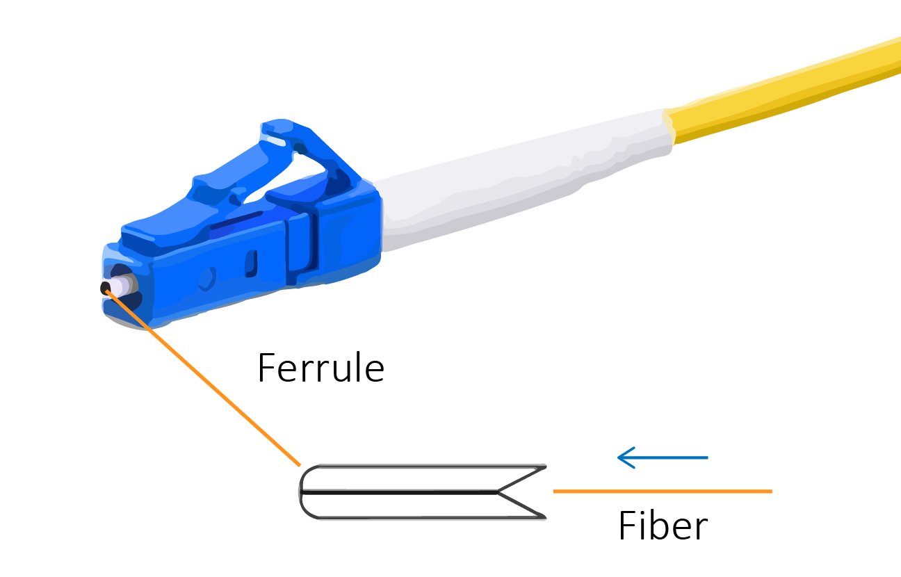
The Role of Ferrules
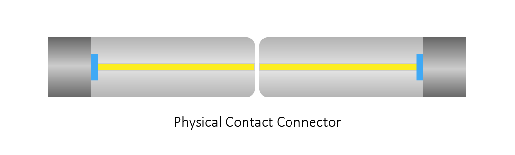
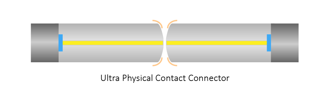
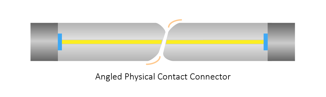
Ferrules, critical components in fiber-optic connectors, play a pivotal role in loss management. Various polishing techniques, such as physical contact (PC), ultra-physical contact (UPC), and angled physical contact (APC), significantly impact loss levels.
PC: suitable for applications with higher IL tolerance due to its convex finish, reducing imperfections.
UPC: provides a reliable signal with lower IL, but repeated mating may increase RL over time.
APC: ideal for low-loss tolerance applications like fiber-to-the-home (FTTH) deployment, effectively channeling back reflections.
It is important to note that APC ferrules may not mate with other polish types, potentially limiting their compatibility with legacy systems. Regardless of the polish type used, maintaining clean ferrules is of paramount importance for minimizing connectivity loss, particularly before and after testing procedures.
Staying within the Loss Budget
Maintaining a cumulative acceptable loss, also known as the "loss budget," is critical for the network's smooth functioning. Light source and power meter measurements exceeding the loss budget necessitate a thorough examination to identify root causes of loss.
Conclusion
In the dynamic realm of high-speed networking, conquering connectivity loss is non-negotiable for optimal performance. Partner with ProLabs for reliable and efficient networking solutions that power your success. Together, we'll ensure seamless connectivity and unparalleled performance in your high-speed network.
Embrace the new era of 400G transport and data center interconnect. The advent of 400G ZR and Open ZR+ modules has unlocked the potential of open pluggable DWDM optics, allowing for seamless IP over DWDM and data center interconnect services.
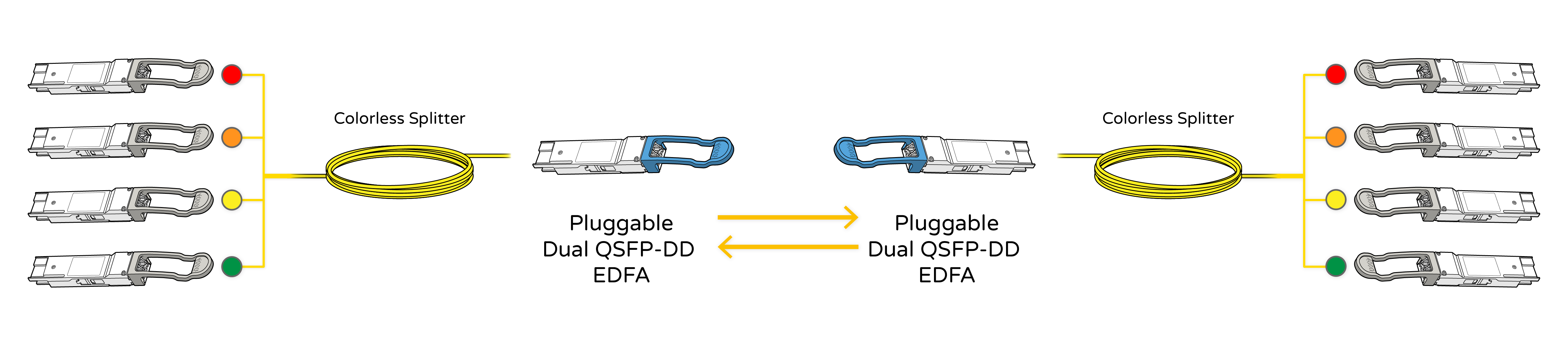
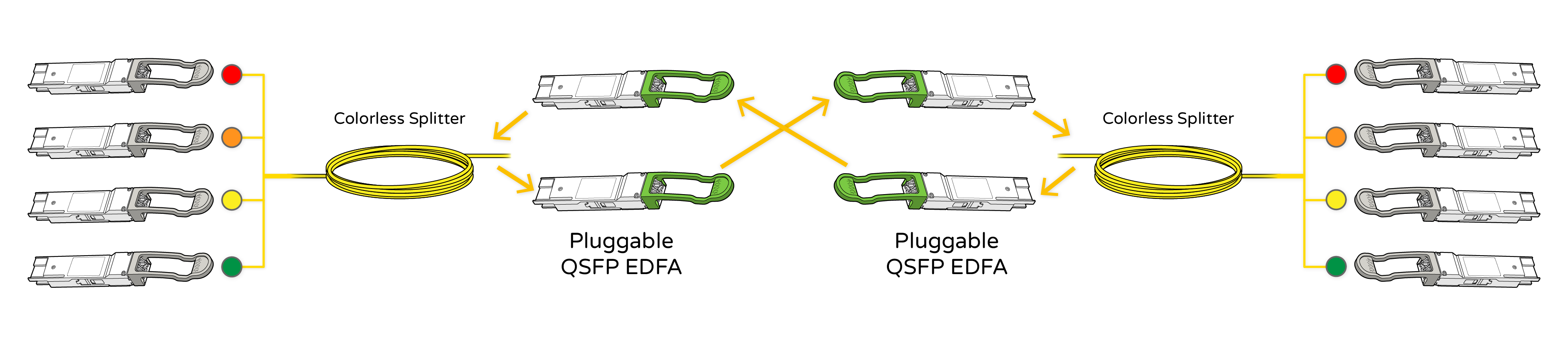
Introducing ProLabs' modular line system, designed to streamline your DCI deployments. Our fully pluggable solution combines the convenience of pluggable optical amplifiers (available in QSFP-DD Dual Pluggable or QSFP Pluggable form factors) with an easy-to-use 8-channel optical power colorless splitter and LC parking adapter.
Explore our cutting-edge pluggable modular line system, and experience effortless optimization of your DCI and IP-over-DWDM deployments.
QSFP-DD Dual Pluggable EDFA
QSFP-DD Dual Pluggable EDFA Booster amplifier for DWDM, Duplex LC, Input power -20dBm to 0dBm, Nominal gain +20dB
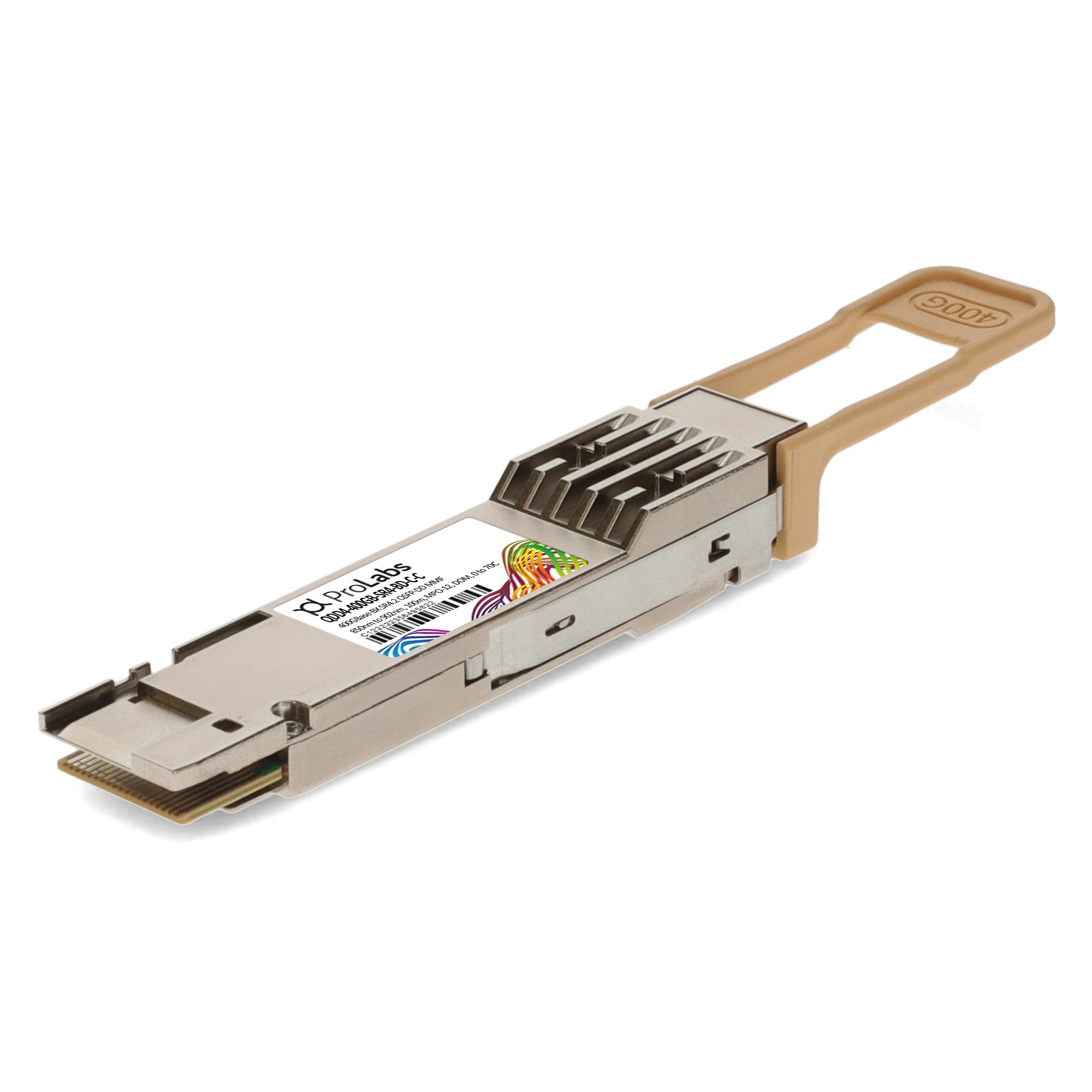
Demand for data rates greater than 100 Gb/s is being driven by cloud and AI applications, resulting in the transition to high-speed, low-power 400 Gb/s interconnects. To support the short-reach application space inside data centers, the optical fiber industry developed two IEEE 400G Ethernet standards, 400G SR4.2 and 400G SR8.
400G SR4.2
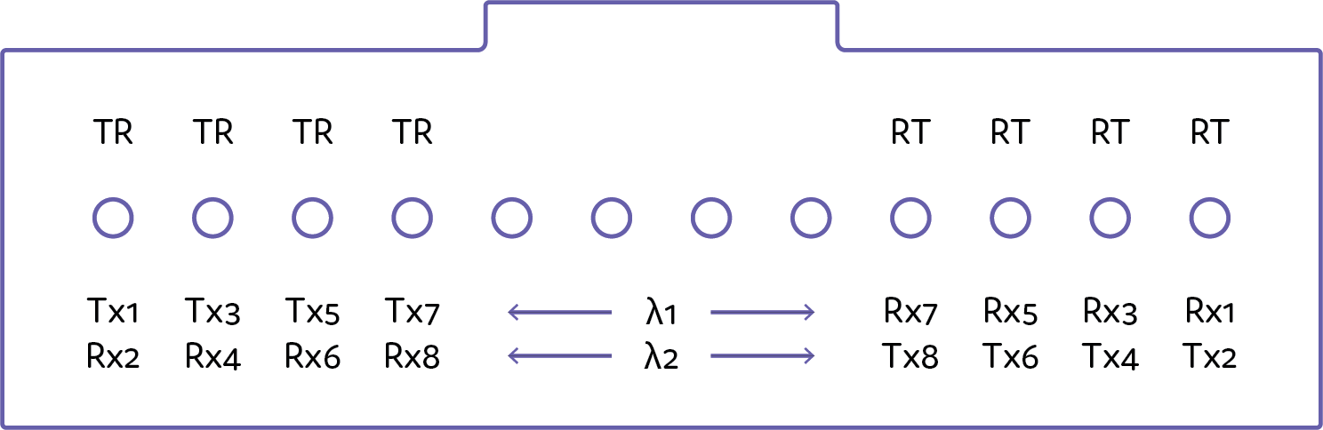
400G SR4.2 is a 4-pair, 2-wavelength multi-mode solution supporting reaches of 70m (OM3), 100m (OM4), 150m (OM5). It is the first IEEE 802.3 solution to use multiple pairs of fibers and multiple wavelengths, as well as the first Ethernet standard to use two short wavelengths to double multi-mode fiber capacity from 50 Gb/s to 100 Gb/s per fiber.
The 400G SR4.2 operates on the same cabling as 40G SR4, 100G SR4, and 200G SR4. On each fiber, bidirectional transmission is used, with each wavelength traveling in opposite directions. As a result, each active position at the transceiver serves as both a transmitter and a receiver, resulting in a bidirectional optical configuration of eight optical transmitters and eight optical receivers in 400G SR4.2.
400G SR4.2 fiber interface
400G SR8
400G SR8 is an 8-pair, 1-wavelength multi-mode solution with 70m (OM3) and 100m (OM4) reach (OM4 & OM5). It is the first IEEE fiber interface to employ 8 fiber pairs. Unlike the 400G SR4.2, it operates on a single wavelength (850nm), with each pair capable of transmitting 50 Gb/s. It also has two optical lane arrangement variants: a 24 fiber MPO configured as two rows of 12 fibers & a single-row MPO-16.
Additionally, 400G SR8 provides both flexibility and higher density that supports fiber shuffling in 50G/100G/200G configurations, as well as fanout at various I/O speeds for a variety of applications. A 400G SR8 QSFP-DD transceiver can be configured to operate as 400G SR8, 2x200G SR4, 4x100G SR2, or 8x50G SR.
While 400G SR4.2 and 400G SR8 are both multi-mode solutions for 400G Ethernet, they have several features in common as well as significant differences, which are covered in the table below.
Although 400G SR8 is technically simple, a ribbon patch cord with 16 fibers is required. It is typically built with 8 VCSEL lasers and does not include a gearbox, which keeps the overall cost of modules and fibers low. In comparison, 400G SR4.2 is technically more complex, resulting in a higher overall cost of related fibers or modules, but it can support a longer reach.
Increasing Higher Speed Ethernet with 400G SR4.2 and 400G SR8
Both 400G SR4.2 and 400G SR8 support 400G Ethernet and scale up multi-mode fiber lines, assuring the feasibility of optical solutions for a variety of demanding applications as multi-mode fiber develops to meet rising speed and capacity demands.
With the two IEEE 802.3cm standards, it provides a smooth path for Ethernet evolution to enhance cloud-based services and applications. These future advancements indicate that they will be able to support even higher data rates as they progress to the next level. Thus, eventually having 400G SR4.2 and 400G SR8 pave the way for future of 800 Gb/s Ethernet.
Organizations operating data centers and high-performance compute environments are actively seeking cost-effective and energy-efficient upgrade solutions that deliver exceptional performance.
The latest innovation from ProLabs is the QSFP56 FR4 transceiver, which addresses these requirements by providing an upgraded path from existing 100G CWDM4 to 200G. This transceiver stands out as a low-power consumption product equipped with a high-bandwidth module, enabling seamless 200G Ethernet connectivity over single-mode fiber links.
With the exponential growth of bandwidth and the need for low latency, sensitive applications are driving the expansion of 5G wireless networks. As 5G offers increased speed, reduced latency, and improved flexibility, it has become a game-changer in communication technology.
But to fully realize the potential of 5G, a robust wired network is crucial, and this is where 400G optics comes into play. In this article, we explore the connection between 5G and 400G optics and delve into the applications that are driving their transformative impact.
What is 5G?
5G, the cutting-edge wireless technology, offers a potent combination of speed, reduced latency, and enhanced flexibility. It signifies a revolutionary communication shift, fundamentally transforming data transmission and paving the way for a myriad of novel applications. Beyond network computing, the improved reliability and user experience of 5G empower distributed computing and unlock a world of innovation and disruption across industries.
What is 400G?
400G optics emerges as a solution to address the escalating bandwidth demands stemming from the widespread adoption of digital applications. With a fourfold improvement in maximum data transmission speed over 100G, 400G technology aids network infrastructure providers in meeting the ever-growing bandwidth requirements in mass production data centers and core networks.
Understanding 5G and 400G
While wireless connections are integral to a 5G network, a robust wired network is crucial for its practical implementation and success. Seamless low-latency connections between devices, data centers, and the cloud necessitate effective and scalable edge computing paradigms. Consequently, higher fiber densification at the edge and increased data rates on existing fiber networks become imperative. Thankfully, 400G bridges these networking gaps, enabling streamlined operations and enhanced capacity delivery to the network edge for carriers, multiple-system operators (MSOs), and data center operators.
Applications Driving 400G Transformation in 5G
1. Video Streaming
With the rising demand for high-quality content and buffer-free video streaming, the rapid deployment of 5G technology takes the viewing experience to new heights. To support this, 400G Ethernet is crucial in ensuring reliable power, efficiency, and density, allowing digital streaming service providers to meet increasing bandwidth requirements.
2. Virtual Gaming
5G opens up a captivating future for gamers, enabling high-definition live streaming and low-latency gaming experiences. By leveraging the power of 5G networks and the cloud, gamers can enjoy high-definition games without the need for expensive devices or powerful computers.
3. The Internet of Things (IoT)
The integration of IoT across industries has revolutionized various sectors. 5G, coupled with IoT, makes previously impossible applications feasible. However, to meet the bandwidth demands and allow for real-time responsiveness, the network infrastructure must support high-end flexibility. 400G optics plays a vital role in providing the necessary capacity and reliability for IoT devices to function seamlessly.
Conclusion
The convergence of 5G and 400G technologies marks a significant milestone in connectivity. As 5G networks rapidly expand and digital applications flourish, the power of 400G optics becomes essential in supporting the massive bandwidth demands. Together, they unleash a world of opportunities across industries, revolutionizing video streaming, gaming experiences, and IoT innovation.